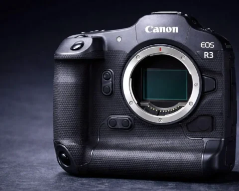
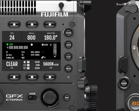
A new patent application published by Canon indicates a variable built-in ND filter apparatus. The camera demonstrated iOS the EOS R3. Hence there’s a high chance that this ND filter will be implemented into the upcoming Canon R3 Mark II.
Canon EOS R3 Mark II With Built-In ND Filter
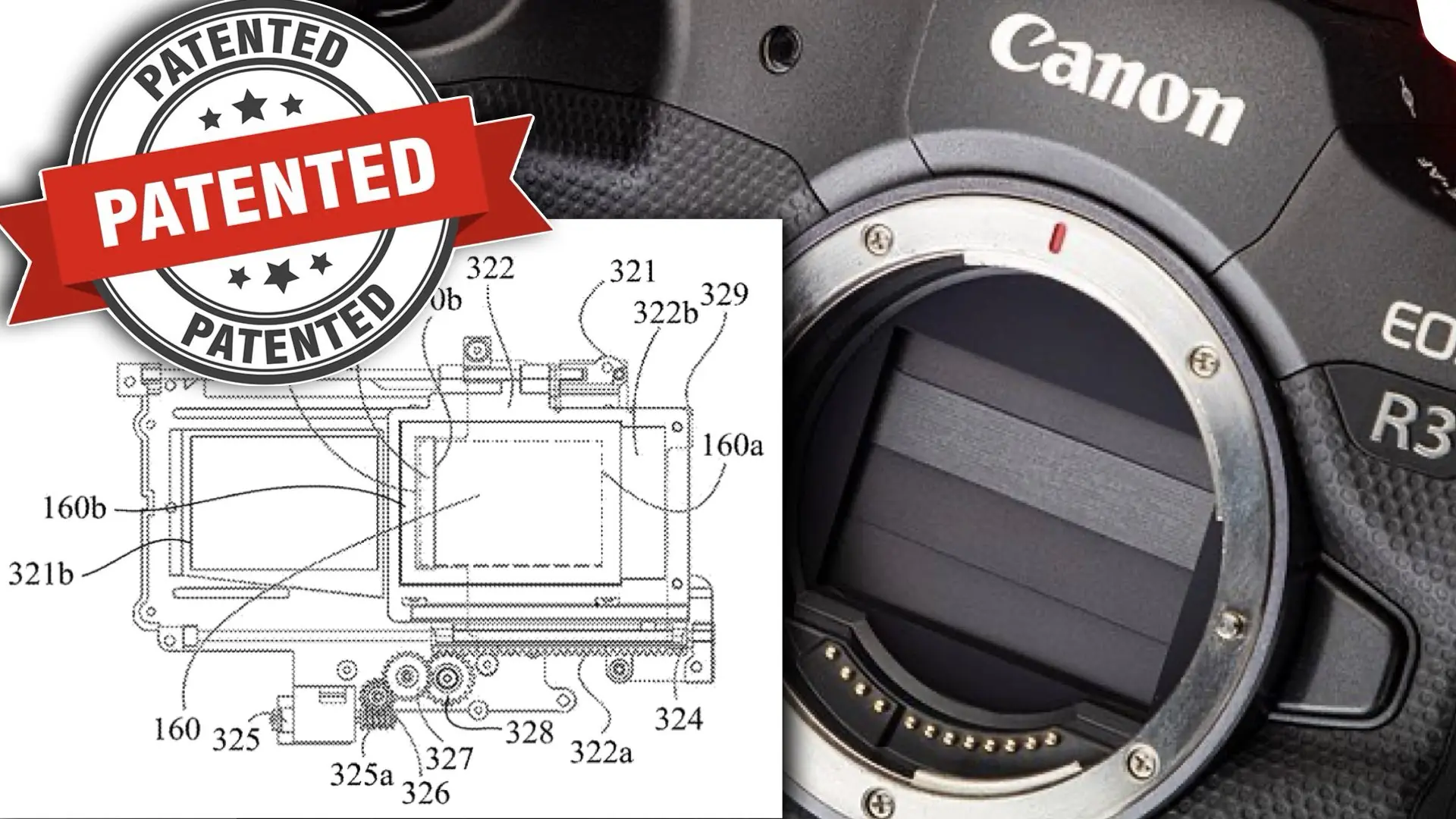
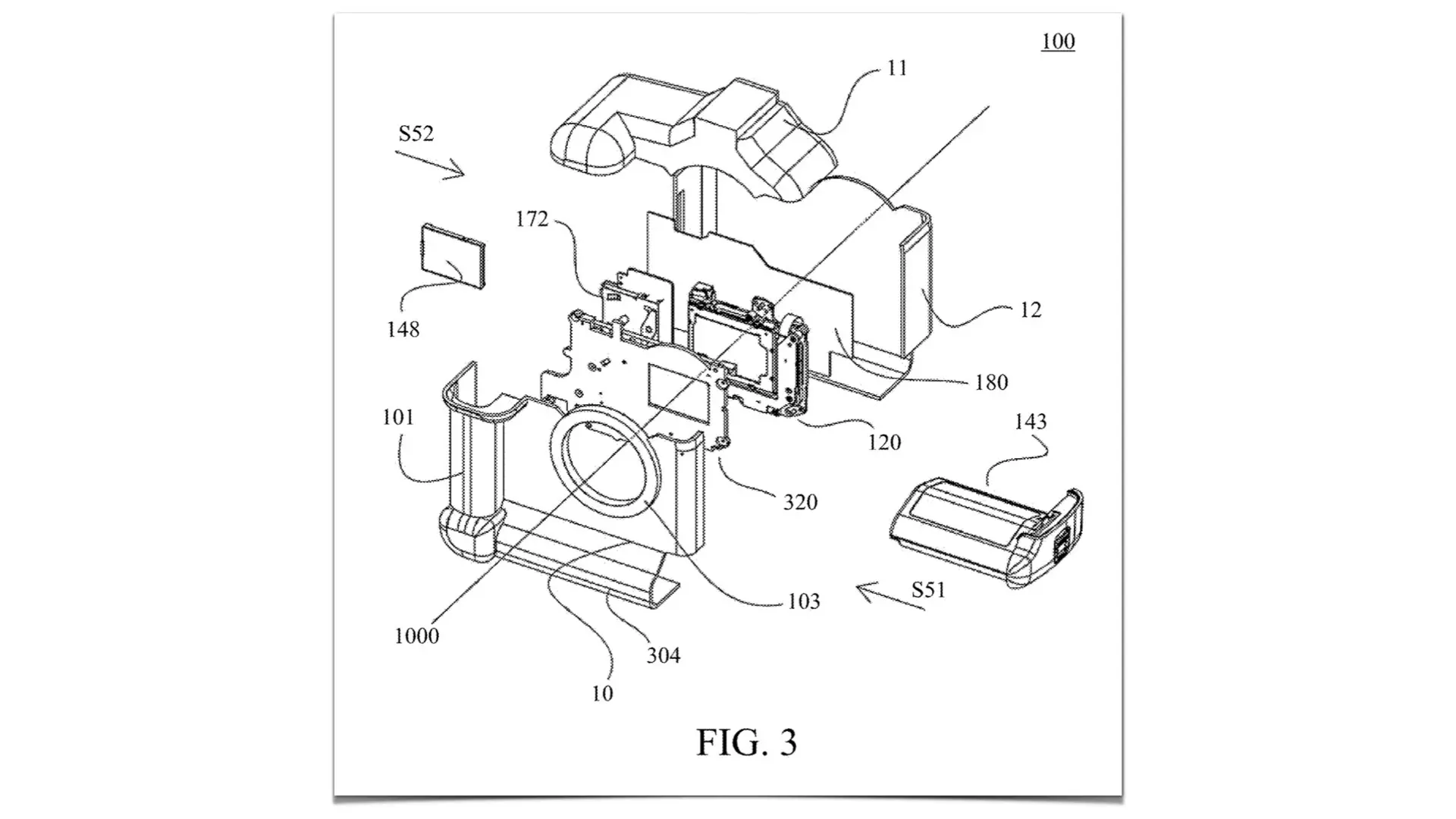
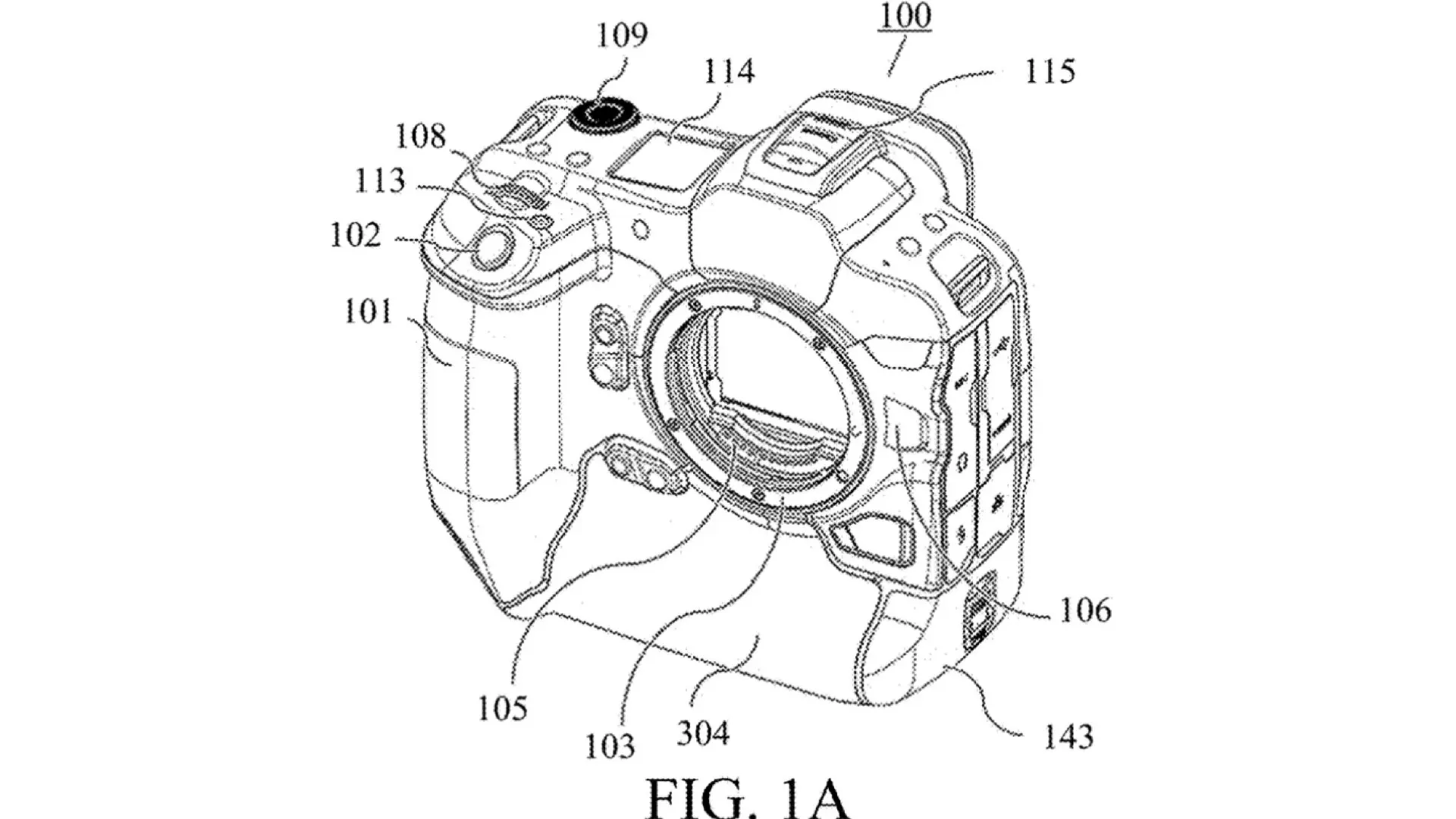
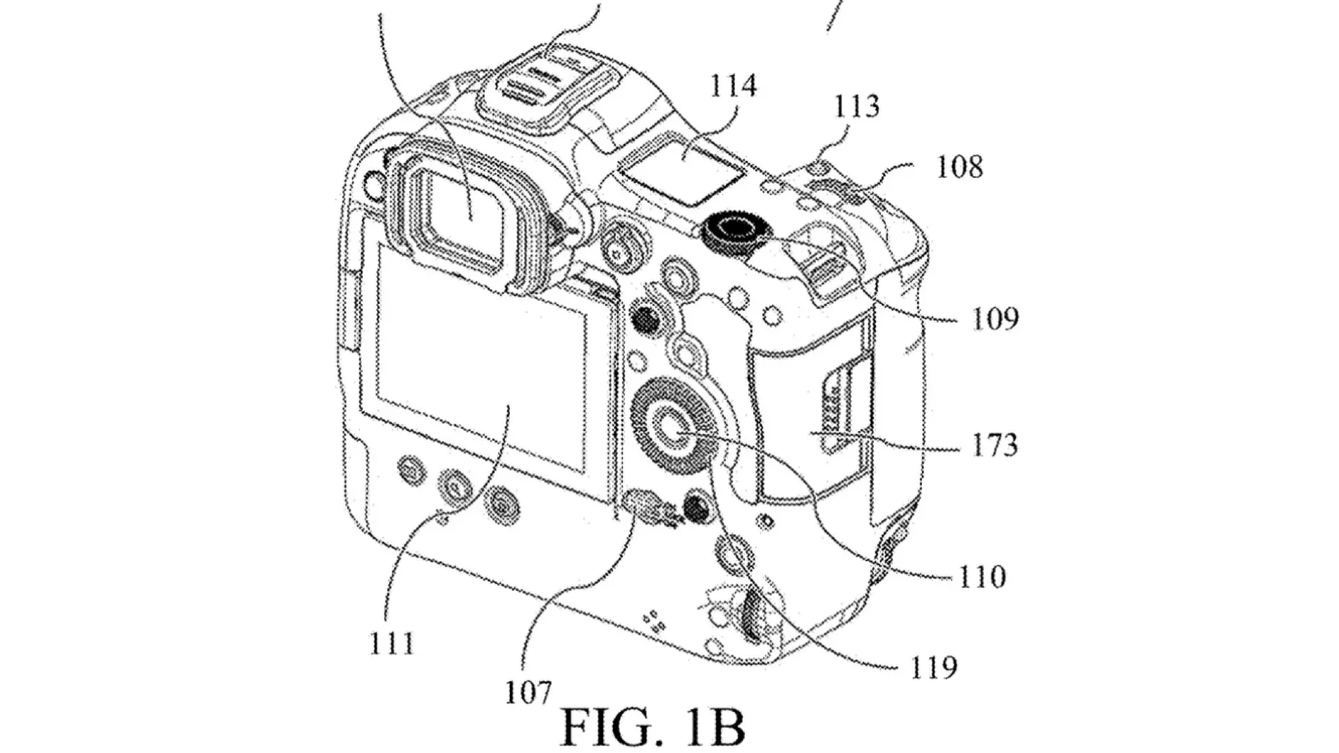
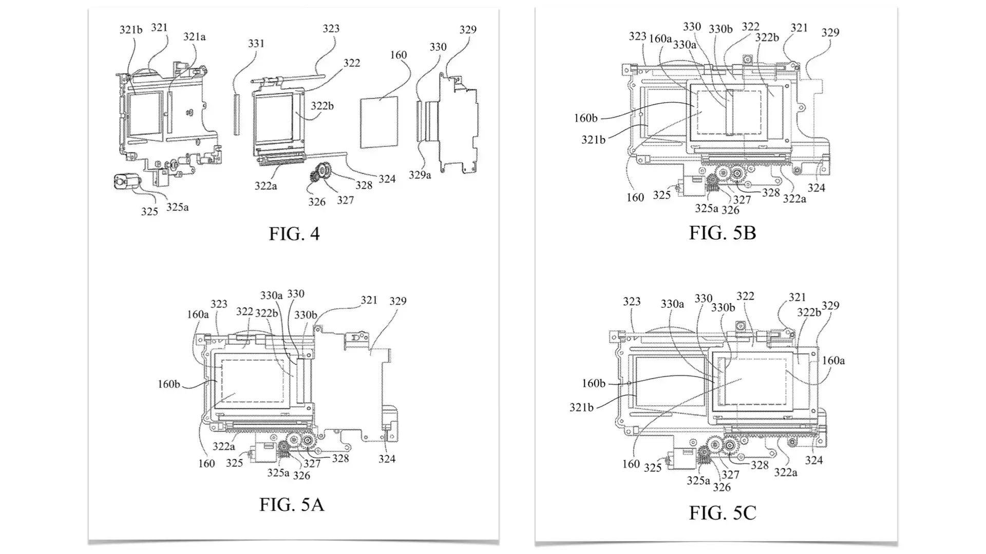
Two weeks ago, Canon published a patent application titled “IMAGE PICKUP APPARATUS” which describes an apparatus of built-in ND filter. This is not the first time Canon patented this kind of apparatus, however, now it seems Canon is ready to implement this essential solution in their mirrorless lineup and not just focus on the Cinema EOS lineup. The camera shown in this application is the R3. Thus, we assume that this built-in ND filter will be implemented in the upcoming R3 Mark II (R1 X) that will be introduced in 2025. Below you can explore selected patent’s citations and drawings.
Abstract
An image pickup apparatus includes an image sensor, an optical filter, a holder configured to hold the optical filter, a driving unit configured to move the holder, and a first elastic member disposed outside an imaging range. The driving unit moves the optical filter between a first position inserted into the imaging range and a second position retracted from the imaging range. The first elastic member comes into contact with at least a portion of the first surface of the optical filter, in a case where the optical filter moves from the first position to the second position, or in a case where the optical filter moves from the second position to the first position.
Background/Summary
An image pickup apparatus according to one aspect of the disclosure includes an image sensor, an optical filter, a holder configured to hold the optical filter, a driving unit configured to move the holder, and a first elastic member disposed outside an imaging range. The driving unit moves the optical filter between a first position inserted into the imaging range and a second position retracted from the imaging range. The first elastic member comes into contact with at least a portion of the first surface of the optical filter, in a case where the optical filter moves from the first position to the second position, or in a case where the optical filter moves from the second position to the first position.
Design of the ND-filter
Here’s a selected part that elaborates on drawing 5 which demonstrates how the filter functions: “Referring now to FIGS. 5A to 5C, a description will be given of a state transition of the optical filter unit 320. FIGS. 5A to 5C explain the state transition of the optical filter unit 320. FIG. 5A illustrates an inserted state (used state, first position) where the optical filter 160 is inserted into an imaging optical path (imaging range). FIG. 5B illustrates a middle state (middle position) while the optical filter 160 is moving from the inserted state (first position) to a retracted state (second position). FIG. 5C illustrates the retracted state (unused state, second position) where the optical filter 160 is retracted from the imaging optical path. In this manner, the optical filter 160 can move between the first position inserted into the imaging range and the second position retracted from the imaging range by the motor 325. In the inserted state of FIG. 5A, when the user presses down the multifunction button 113, the optical filter unit 320 starts moving so as to transition to the retracted state. A rotation of the motor 325 is transmitted to the rack gear forming portion 322a of the optical filter holder 322 through the first gear 326, the second gear 327, and the third gear 328. The optical filter 160 moves from the inserted state (FIG. 5A) via the middle state (FIG. 5B), and reaches the retracted state (FIG. 5C), while being guided by the upper portion rail 323 and the lower portion rail 324. The optical filter 160 that has reached the retracted state receives a detection signal of a position sensor (not illustrated) and stops. In inserting the optical filter 160 again, the user presses down the multifunction button 113 in the retracted state illustrated in FIG. 5C. Thereby, the motor 325 rotates in a direction opposite to that of the above operation, and the optical filter 160 reaches the inserted state illustrated in FIG. 5A via the middle state illustrated in FIG. 5B. The optical filter 160 that has reached the inserted state receives the detection signal of the position sensor (not illustrated) and stops, similarly to the retracted state.
Summary
We would bet on it! This means that we are confident that the Canon EOS R3 Mark II will hold this patent thus allowing shooting to utilize variable built-in ND filters even for mirrorless not-high-end models.

