A new patent application by Panasonic suggests an advanced version of the Lumix BGH1 and BS1H. That means, a boxy-style cinema camera with a grip and a screen, dedicated to hand-held shooting. All details are below.
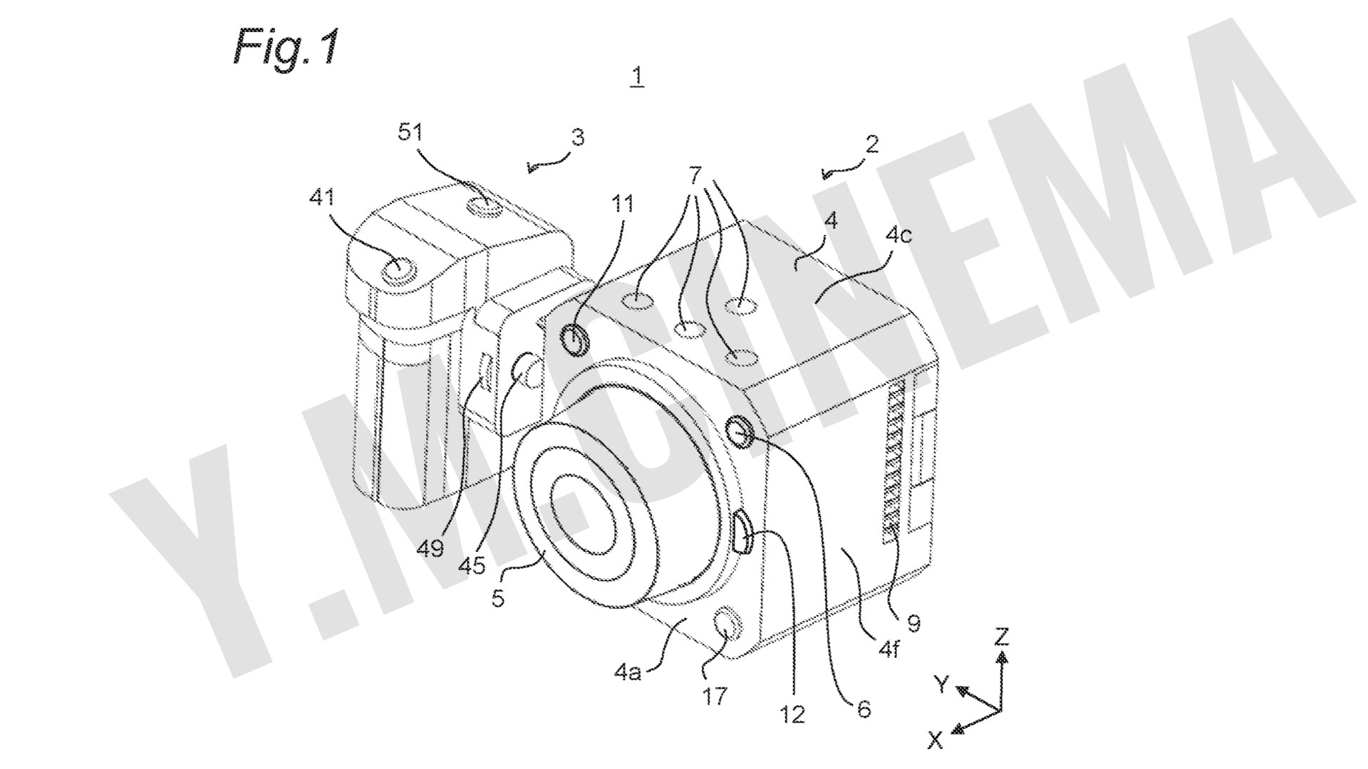
Panasonic Box Cinema Camera patent: FIG. 1 is the perspective diagram of camera 1 in the state where grip part 3 is detached from camera main body 2, taken when camera 1 is seen from obliquely above on the right front side thereof.
New patent: Box cinema camera
Panasonic is trying to upgrade the Lumix BGH1 and BS1H and allow shooters a better boxy-style cinema camera for hand-held filmmaking. The patent is titled “Imaging Device” and presents a new kind of box cinema camera with a grip and a screen. As stated: “An imaging device includes a camera main body, an imaging sensor, a grip part, and an output part. A camera’s main body includes a housing, and an imaging sensor is disposed of inside the housing. The imaging sensor converts light into an electric signal. A grip part is attachable and detachable to/from the housing. An output part outputs an imaged image based on the electric signal. In an attachment and detachment direction of the grip part, the imaging sensor is disposed of in a central portion of the housing”.
Panasonic Box Cinema Camera patent: FIG. 2 is the perspective diagram of camera 1 in the state where the grip part 3 is detached from the camera main body 2, taken when camera 1 is seen from obliquely above on the left rear side thereof.
Dedicated to hand-held shooting
As described in the application: “For the above stationary imaging device, JP2018148545A (the patent of the previous boxy-style camera) does not take into consideration the realization of two types of shooting style that are fixed shooting and hand-held shooting. Assuming that the stationary imaging device can realize these two types of shooting styles, the stationary imaging device can provide a user with various shooting styles for the user. The stationary imaging device is however designed to be used for fixed shooting as a precondition and, especially, when the box camera is directly griped and hand-held shooting is thereby executed, the griping itself tends to be unstable. Furthermore, for example, the user’s fingers touch the lens, and the focus and the aperture value may thereby be varied, or the fingers may cover the lens to be shot, and the hand-held shooting is therefore difficult. Devices such as a large-scale optional item are therefore necessary in the case where hand-held shooting is tried to be executed using the stationary imaging device. Therefore, the present disclosure provides an imaging device capable of easily realizing two types of shooting styles. An imaging device in one aspect of the present disclosure includes a camera main body that includes a housing, an imaging sensor that is disposed inside the housing and that converts light into an electric signal, a grip part that is attachable and detachable to/from the housing, and an output part that outputs an imaged image based on the electric signal. In an attachment and detachment direction of the grip part, the imaging sensor is disposed of in the central portion of the housing”. Explore the slides below with the patent’s figures:
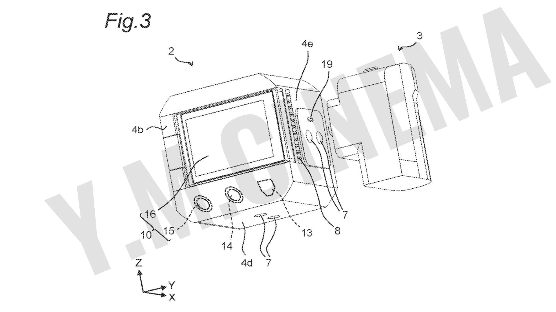
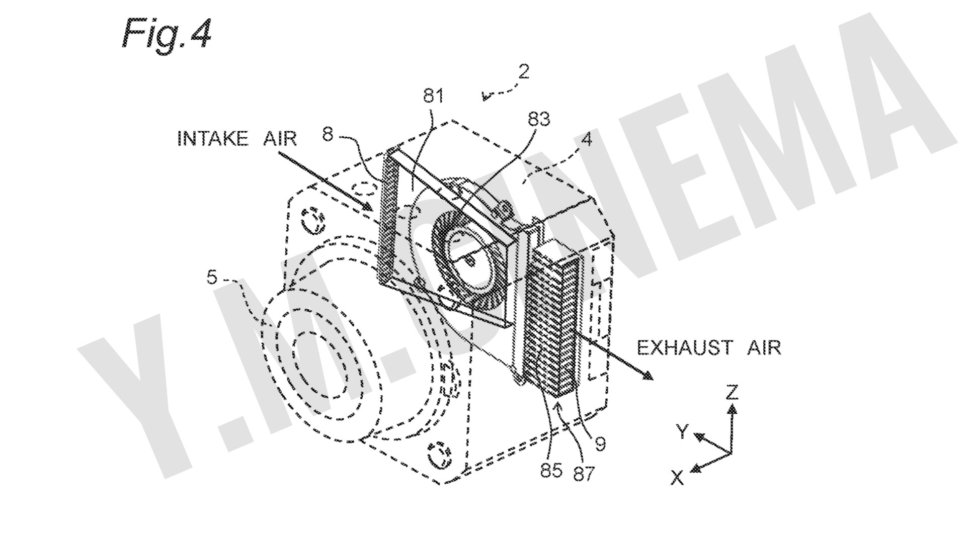
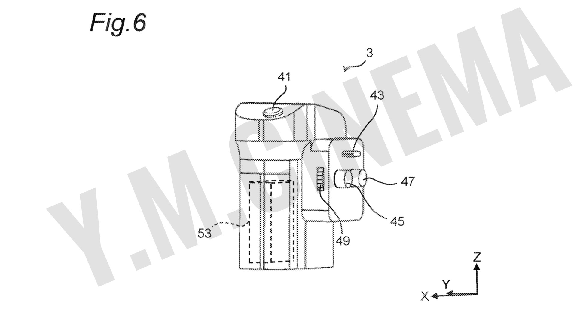
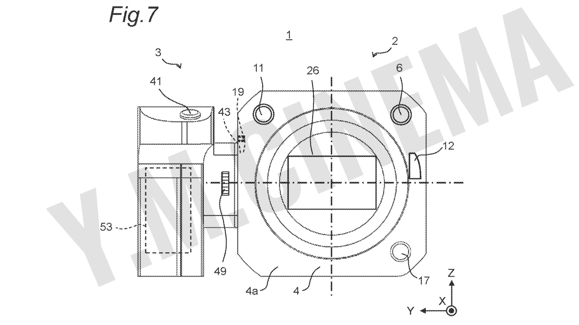
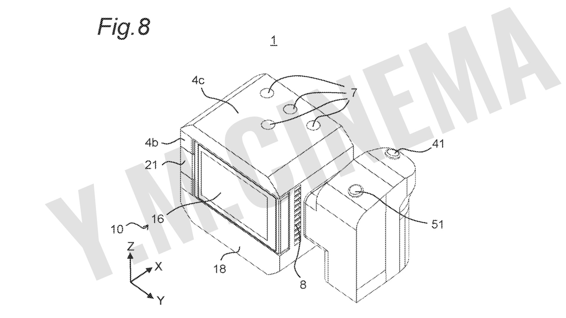
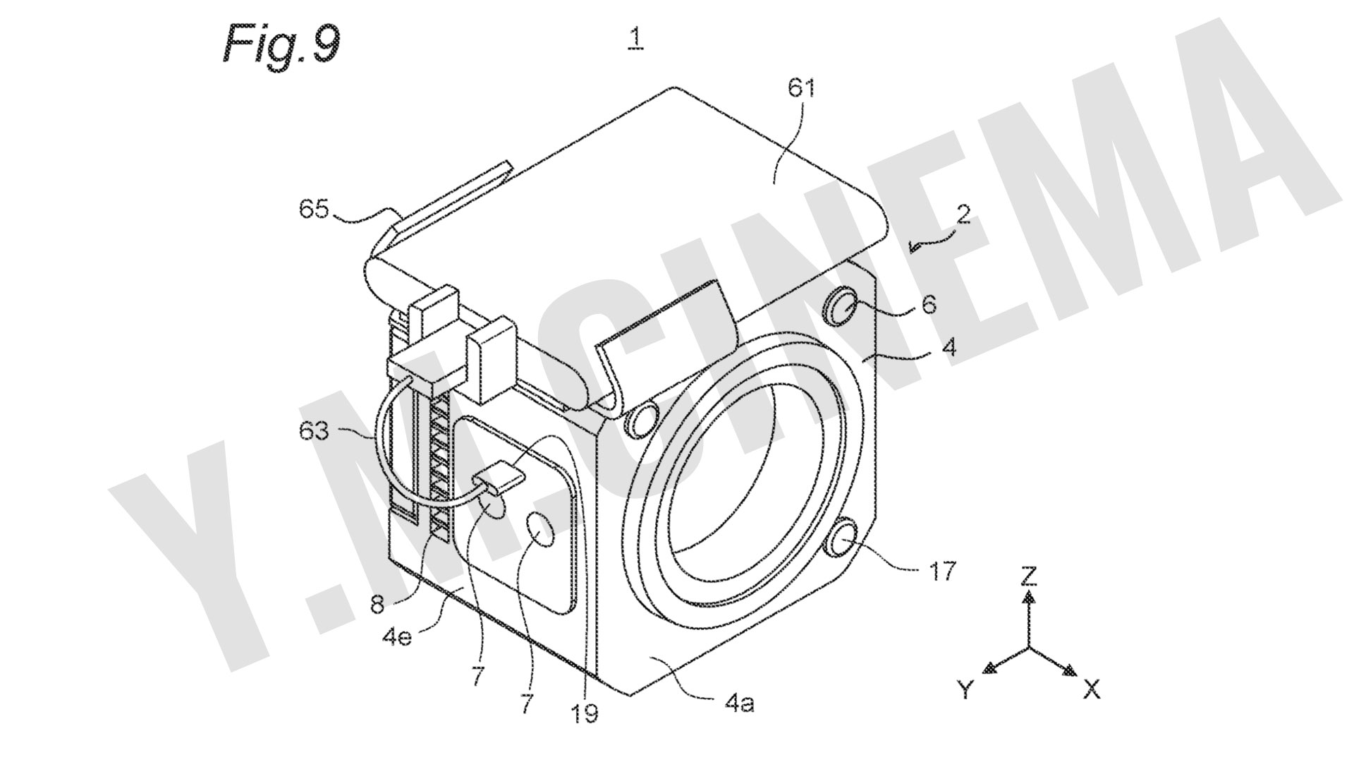
FIG. 1 is the perspective diagram of the camera 1 in the state where a grip part 3 is detached from a camera main body 2, taken when the camera 1 is seen from obliquely above on the right front side thereof.FIG. 2 is the perspective diagram of the camera 1 in the state where the grip part 3 is detached from the camera main body 2, taken when the camera 1 is seen from obliquely above on the left rear side thereof.Panasonic Box Cinema Camera patent: FIG. 3 is the perspective diagram of the camera 1 in the state where the grip part 3 is detached from the camera main body 2, taken when the camera 1 is seen from obliquely underneath on the left rear side thereof.Panasonic Box Cinema Camera patent: FIG. 4, a duct part 81 as a cooling flow path is located inside the housing 4, and a cooling fan 83 is located in the duct part 81. The cooling fan 83 causes the external air to be suctioned from the air inlet 8 and causes the suctioned external air to pass through the duct part 81 to be discharged from the air outlet 9. A heat sink 87 including fins is attached inside the duct part 81, and the inside of the housing 4 is efficiently cooled using the heat sink 87.Panasonic Box Cinema Camera patent: FIG. 5 is in the state where the interchangeable lens 5 is detached therefrom. The imaging sensor 26 that converts the light entering the interchangeable lens 5 into an electric signal is located inside the housing 4 of the camera main body 2. The imaging sensor 26 images an object image formed through an optical system of the attached interchangeable lens 5, and forms image data.Panasonic Box Cinema Camera patent: FIG. 6 is a perspective diagram of the grip part 3 taken when the grip part 3 is seen from the right front. The grip part 3 includes a shutter button 41, a second connector 43, a screw 45, a protrusion 47, a dial 49, a function button 51 (FIG. 8), and a battery 53. The visible outline in a transverse section of the grip part 3 has a U-like shape. and the grip part 3 has a shape for the user to easily grip.Panasonic Box Cinema Camera patent: FIG. 7 is a front elevation diagram of the camera 1 in the state where the camera main body 2 has the grip part 3 attached thereto. FIG. 8 is a perspective diagram of the camera 1 in the state where the camera main body 2 has the grip part 3 attached thereto.Panasonic Box Cinema Camera patent: FIG. 8 is a perspective diagram of the camera 1 in the state where the camera main body 2 has the grip part 3 attached theretoPanasonic Box Cinema Camera patent: FIG. 9 depicts an example where, for example, an SSD (Solid State Drive) 61 is connected to the camera main body 2 as an external storage medium.Panasonic Box Cinema Camera patent: FIG. 10 depicts an example where a microphone 71 is connected to the camera main body 2. The microphone 71 is connected to the first connector 19 of the camera main body 2 by a USB cable 77. Audio data formed by the microphone 71 can thereby be transmitted to the camera main body 2, and can be synthesized with the image data formed by the imaging sensor 26. The microphone 71 is detachably supported by, for example, an attachment holder 73, and a plate 73a of a bottom portion of the attachment holder 73 is fixed by a screw 75 in the screw hole 7 located in the fifth face 4e of the camera main body 2.
There’s no info regarding the sensor size. Nevertheless, it looks like a new and exciting LUMIX on the horizon.
YMCinema is a premier online publication dedicated to the intersection of cinema and cutting-edge technology. As a trusted voice in the industry, YMCinema delivers in-depth reporting, expert analysis, and breaking news on professional camera systems, post-production tools, filmmaking innovations, and the evolving landscape of visual storytelling. Recognized by industry professionals, filmmakers, and tech enthusiasts alike, YMCinema stands at the forefront of cinema-tech journalism.
This proves nothing. Not to mention that, based on this, the application is a bunch of bullshit. What are the claims in the patent? Where is the novelty?
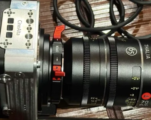
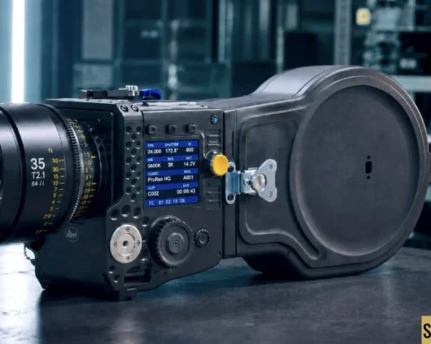
Sony RIALTO 65 is now real enough to see. After the development announcement earlier this week, Sony Cine has now shown the new 65mm sensor block at Cine Gear, giving filmmakers their…
Cinelux SIXTEEN is one of the more interesting film camera concepts we have seen in years because it attacks the exact weakness that keeps 16mm film away from many modern productions. The…
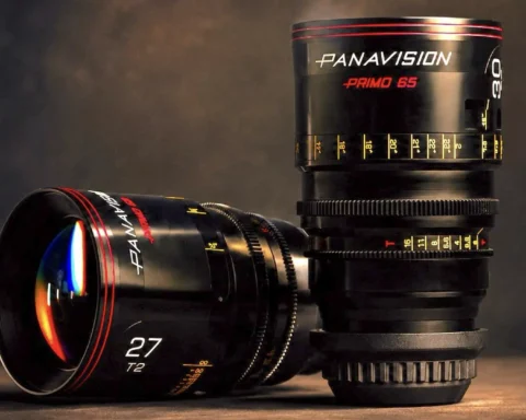
Panavision has announced the new Primo 65 lens series, a fresh family of spherical cinema primes designed to bring the celebrated Primo optical identity into the expanding world of 65mm digital cinematography.…
Sony has announced the development of RIALTO 65, a new 65mm format image sensor block designed to expand the VENICE 2 digital cinema camera system into a much larger imaging platform. The…
NVIDIA has introduced RTX Spark, a new superchip platform for thin Windows laptops and compact desktops, and the claim aimed at creators is unusually direct: 12K 4:2:2 video editing on a portable…


![RED (Nikon) V-Raptor [X] 8K VV is Netflix Approved](https://ymcinema.com/wp-content/uploads/2024/05/red-v-raptor-x-nikon-netflix-approved-1024x576.jpeg)


This proves nothing. Not to mention that, based on this, the application is a bunch of bullshit. What are the claims in the patent? Where is the novelty?
Trash.
It’s an unironically good thing that there’s a negative comment on this post.
Panasonic should be held accountable for how worthless this patent is. Corporations being corporations once again.